
 Reply with Quote
What's the part number of the $120.00 milling machine, Scott? I can't find it on Tormach's website!Originally Posted by Scott_M

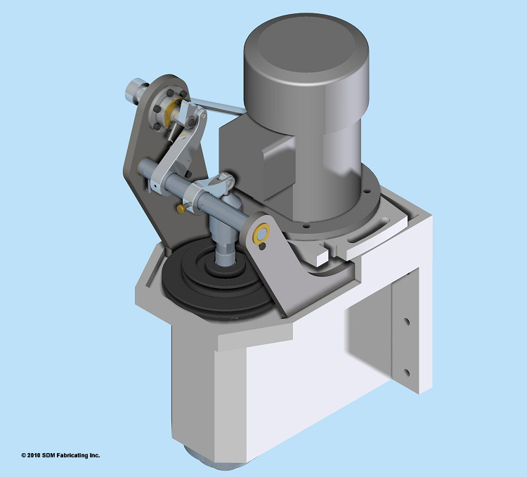
But seriously, that is a seriously nice looking drawbar mechanism. What do you estimate the completed build cost to be?
Randy